-
 Pendent: Terrain analysis: Slopes, Aspects, etc
Direct access to online help: Pendent
Access the application from the menu: "Tools | Terrain interpolation and analysis | Compute slopes, aspects, etc"
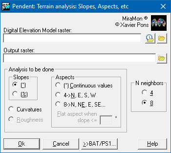
Presentation and options
This application calculates, based on a Digital Elevation Model, several Digital Models (slope: MDP, aspect: MDO, etc) which are derived from the elevations, in ordre to describe and to characterise the relief.
The application can produce the following Digital Models:
- Slope (°). the output file contains for each cell the maximum gradient as a function of the planes defined by the heights of the neighboring cells. The calculated values are given in degrees.
- Slope (%). As for the previous case but the result is given in percent (%). The percentage slope indicates the relative vertical change with respect to the horizontal displacement (and not with respect to the displacement along the inclined plane). For example a slope of 45° corresponds to a gradient of 100%. If for some reason the user wishes to express the slope as a percentage of the displacement along the inclined plane then the slope should be calculated in degrees and then, using CalcIMG, the percentage can be found by calculating 100*SING([MDP]), where MDP is the name of the slope file in degrees.
- Aspects (° + plane). The output file contains in each cell the aspect relative to North of the plane of maximum slope. More formally, the aspect is the angle between the north vector and the projection onto a horizontal plane of the vector perpendicular to the plane (normal vector) defined by the heights of the neighboring cells. This angle is measured from north, clockwise: an aspect of 90° implies that the surface at that point faces East, whereas an aspect of 180° is facing South and an aspect of 270° looks West. When the area is completely flat, the aspect is undefined and by convention the application assigns a value of -1 to the cell.
It should be noted that both values of 0° and those of 360° face North, a fact that leads to difficulties interpreting the displayed image if a continuous tone palette, like a grey scale, is used for visualization. Unless the user is already accustomed to these types of aspect images it is recommended to run the option 'Aspects (4 directions + plane)' as well and to compare the results with the result calculated in degrees but displayed using the "Orienta.dbf" palette.
- Aspects (° + plane). This option is very similar to the previous one, but usually better since it considers as flat not only areas which are exactly horizontal but also those areas with a gentle slope. Effectively it makes little sense to consider the aspect of an area with a slope as small as 0.5°: geomorphologically the area is flat.
- Aspects (4 directions + plane): The continuous Aspect Model is reclassified into four aspects: North, East, South and West. The flat, or practically flat, areas (defined with /PEN_PLA=) are assigned a value 0.
- Aspects (8 directions + plane): The continuous Aspect Model is reclassified into eight aspects: N, N-E, E, S-E, S, S-W, W and N-W. The flat, or practically flat, areas (defined with /PEN_PLA=) are assigned a value 0.
IMPORTANT NOTE FOR ALL THE ASPECT OPTIONS:
If the user wishes to establish correlations between the aspect and the vegetation distribution then, normally, it makes more sense and produces better results to forget the aspect and to calculate the solar radiation instead. This can be found using the appropriate MiraMon application (InsolDia). The solar radiation is a much better approximation of the aspect factors that condition the distribution of the vegetation. It is a different matter if the user wishes to correlate the aspect with other variables that may have a more direct relation with the vegetation distribution, such as the directions of the prevailing winds.
The optional parameter "/PEN_PLA=" permits the user to
indicate the threshold slope below which an area is to be considered
flat and its aspect undefined. "/PEN_PLA=" is defined in degrees; the default value is 2°.
To specify that only a gradient of 0° should be regarded as flat and aspects should be calculated for all other areas then it is necessary to set "/PEN_PLA=0" in the command line or to define in the dialogue box wPendent: Orientació plana en pendent (flat aspect on slope)<=0
Note: if the "/PEN_PLA=" value that the user wishes to apply is only
known in percent and not in degrees then it is necessary to convert it to degrees using the following expression arctan(P_percent/100); making sure that the calculator is operating in degree mode. If the calculator only works in radians then multiply the result by 28.6479.
- Curvature. The resulting file contains in each cell the curvature of the terrain. This value is 0 for perfectly flat areas (whether horizontal or inclined), is negative for convex areas and positive for concave surfaces. A hill top is a convex area, ie., the vectors perpendicular to its surface diverge, whilst the bottom of a valley is concaved. The curvature is calculated using a Laplacian operator. The Digital Curvature Model is more sensitive to the presence of NoData values amongst the neieghbors than other models obtained using this MiraMon application. For this reason it is possible that for some cells for which the MDE can be used to generate slope even though there are NoData values in the vicinity, MDCurvatures may not be able to calculate curvature and will assign NoData values to those cells. In other words, when the original file contains NoData areas then it is possible that the number of cells in the output file marked with NoData may be greater when using MDC than when using MDP.
The higher the value of the curvature, in absolute magnitude, the greater the curvature in the surrounding area, whether concaved or convexed. Since the curvature calculated from MDEs generally produces values with a very reduced range, the result is multiplied by a factor of 1000.
For all of these options the user may chose to define the relief morphology as a function of the elevations of the 4 nearest neighbors (above, below, left and right) or considering also the next four nearest neighbors taken diagonally (upper left and right, lower left and right). In the latter case (considering 8 neighbors) the results are usually a little smoother but they are also generally more realistic due to the fact that a wider geographic area is taken into account and because the analysis is less sensitive to directionality (pixelation) of the original MDE raster.
The calculations for the pixels around the border of the image (columns 0 and ncol-1, and rows 0 and nfil-1) are only approximate. If mosaics of different MDEs are to be created an overlap should be used. Similarly the calculations around the edge of a NoData area are also less exact because there are less neighboring values to use.
See also the following related applications:
- Terrain Analysis:
- Generation of Digital Elevation Models:
- Shadow effects in Digital Elevation Models and Thematic Maps:

Dialog box of the application
Syntax
Syntax:
- Pendent DEM OutputFile AnalysisType NumberNeighbours [/PEN_PLA]
Parameters:
- DEM
(Digital Elevation Model -
Input parameter): Digital Elevation Model raster file
- OutputFile
(Output -
Output parameter): Raster file containing the output from the terrain analysis.
- AnalysisType
(Analysis type -
Input parameter): Option that indicates the choice of analysis to be carried out:
- 1: Slope (°)
- 2: Slope (%)
- 4: Aspect (° + plane)
- 5: 4 aspects
- 6: 8 aspects
- 7: Curvature
NumberNeighbours
(Neighbors number -
Input parameter): This parameter can value 4 or 8 depending on the number of neighbors to be used in the calculations related to the central pixel.
Modifiers:
/PEN_PLA=
(Flat slope)
For calculating aspect, allows the user to indicate the value of the slope below which the area is considered as flat (horizontal) and the aspect of that point undefined. The default value is 2°. To only consider perfectly flat surfaces as having no aspect it is necessary to set this parameter to 0°. (Input parameter)