-
 LinArc: Line topology building and conversion between ARC/NOD and VEC files
Direct access to online help: LinArc
Access the application from the menu: "Edit | Build topology | Arcs/Nodes"
Presentation and options
This application performs the conversion between VEC files containing lines and Top-MiraMon structured vector files (ARC and NOD). Both file formats are supported by MiraMon. VEC files are a superset of the Idrisi ASCII VEC files.
Options detailed description:
From ARC to VEC (option 1):
Converts an ARC family of topologically structured files to a VEC file, which is an ASCII file containing lines that does not have explicit topological relationships. Attributes in the resulting file can be the graphic identifier, a constant attribute or a field of the ARC database (A.REL and A.DBF). The program supports the existence of more than one database record for each graphic element. In this case it writes as many coincident lines as existing records for this graphic element; every line will have one of the multiple attributes.
De VEC a ARC/NOD (option 2):
Takes a file and structures it topologically, creating nodes where arcs intersect and connecting those under the tolerance limit. Later it saves a topological ARC/NOD family. Original file can be a single VEC file, a single ARC file or a set of VEC and ARC files listed in a list file. This last possibility allows overlaying vector layers. Original database fields are combined in the output database A.DBF, becoming a single field if they have the same name (they get a compatible size and type) or different fields if they have different name. Fields of NODE databases are not inherited in the output file. A VEC file is treated as a one-field database of type indicated in the documentation file or with the name that figures in the command line or in the list.
From VEC to ARC/NOD (option 3):
Converts from VEC format to an ARC/NOD family. The only change in the geometry of the original file is the following: given two nodes at a distance lower than the tolerance, the program will consider them as the same node; the position of the second coincidental node will be modified to be equal to the first.
Fusion (option 4):
It joins pairs of arches with the same thematic attributes which share a node and, at the same time, no other arch coincides with the node. This operation does not carry out any topological structuring (it does not divide arches, carry out connections, etc). It is useful for importing files from other formats which display limitations in the number of vertices by object which forces them to make more than one object per strip of vertices due to the fact that as MiraMon has practically no limitations regarding the number of vertices per arch, it is better from a conceptual perspective to join contiguous arches. Please note that a conventional structuring could generate undesired intersections (e.g. roads on two levels that could intersect on one level).
Minimal local Distances (option 5):
Analyses minimal local distances between arcs. It generates a table that can be represented as a frequency histogram of minimal distances; useful to determine snap tolerance thresholds for option 2. It also generates a VEC file of lines that join points of different arcs being at a distance between ThresholdMin and ThresholdMax. This file allows to see all the movements that will be produced on arcs when applying option 2, and thus determine the percentage of automatically correctly solved errors.
The first format consists on ASCII files that do not have topological structure (at least, not explicitly) and that are not linked to databases (every graphic object accepts only one attribute). A document file (DVC) must always exist in order to define the type of graphic object contained in the .VEC files as well as other general parameters.
The second format consist of Top-MM structured vector files, that are binary files usually with arc-node topology. They are linked to a relational database (A.REL, A.DBF, N.REL and N.DBF). In version 3.x, a document file (DVA and DVN) must exist, but in the next versions it is integrated in the corresponding REL file.
If we have a family of structured vectors as the one described above, we can convert it to VEC format (lines) with the Option 1 of the LinArc application. This is necessary to modify the graphic file from MiraMon or when we want the file to be in text format.
Up to version 3.x of MiraMon, line digitizing is done on non structured vectors. The topological structure of arcs and nodes posterior to the digitizing process is such a complex process that it results almost impossible to do it by hand. This task can be done by choosing the Option 2 of the LinArc application.
In some cases, a VEC file can contain lines that implicitly define arcs and nodes, for example when it comes from a conversion of a family of arc-node files to a VEC through Option 1 of LinArc. In this case, we can choose, through Option 3, not to perform the computing task to define the topological relationships to generate ARC/NOD files, so the process becomes much faster. This option can only be used when la topological structure is not essential; it sometimes is the case of line layers such as contour lines. When polygons have to be built over this layer, this option it is possible to use this option only when the VEC file has implicit arc-node topology, due to topological relationships are essential to cicle polygons. Network analysis is another case where the topology is essential.
Option 2 supports a polygon VEC file as input file, but Option 3 does not support it. In the former case, polygon boundaries are treated simply as lines.
The application creates the LONG_ARC field in the database, indicating the length of each arc. The values of the LONG_ARC field is calculated based on the coordinates in the (map) projection and, therefore, do not give the length on the Earth but as they appear on the map, calculated as it would normally be by a computer assisted drawing (CAD) program. In projections such as UTM these calculations are accurate enough for most purposes. For example, within a UTM zone the length of each arc on the map may differ from the length on the terrestrial ellipsoid by a factor between 0.9996 and 1.0009811009).
When the cartographic projection is known (see list of known projections), as well as the LONG_ARC field the application also creates the LONG_ARCE field, that indicates the real length of each arc as calculated over the terrestrial ellipsoid using accurate geodesic criteria. These new field is especially relevant for cartographic projections in which the calculations made on the maps give clearly different values from the real values over the Earth's surface (for example, the Mercator projection) or in map projections where the difference may be small but significant errors may be accumulated when dealing with long lines.
According to the map projection used the application makes LONG_ARC or LONG_ARCE visible and hides the other field, depending on which is the most commonly used measure of length in that projection. These display criteria may be changed in the REL file.
In options 2 and 3, the application deletes the coordinates repeated (only one preserved). Furthermore, entities formed by a single vertex are removed.
Type of tolerance and its application in the application LinArc, option 2
LinArc defines six types of tolerances for 6 different cases that can be founded in the structure of a vector file. This section explains how each type of situation corresponds geometric tolerance and how LinArc applies them in the application (only in option 2).
Very important: all these tolerances are usually unnecessary if one scans correctly using MiraMon tools connection. However, when a file has been digitalized without following these basic rules of connection, or it has been generated with another software that not properly connects the elements can be necessary to apply these tolerances.
- Precision (Fuzzy tolerance) [Prec]
- Minimum distance between vertices. It must be a very small value,
almost infinitesimal.
- Pseudogeneralization tolerance. [T_Psgen] (fig 1.a)
- Tolerance to remove vertices situated upon the same line. (It is a
definition local to each arc)
- Arcs tolerance. [T_Arc]
- Distance than an arc can be moved (Fig 1.b1) or segment can be bended,
generating a new vertex (Fig 1.b2) to connect with another (implies a relationship between arc and others).
- Undershoot tolerance (fig 1.c) (Arc snap tolerance) [T_Usht]
- It is the maximum distance an arc can be extended to connect to
others. (It implies a relationship among one arc and the others.)
- Node snap tolerance (fig 1.d). [T_Nod]
- Minimum distance between nodes. It is the distance from where one node
absorbs or is absorbed by its neighbours. (This implies a relationship
among one node and the others.)
- Dangle tolerance (fig 1.e) [T_Dngl]
- Arcs shorter than this tolerance will be removed if they present one
or two end nodes. (It is a definition local to each arc.)
Fig 1. The figure shows the original vectors in black and the result of the topological structure in red.
- Pseudogeneralization tolerance reduces the number of vertices of the vectors, eliminating alignments.
- Tolerance between arcs tend to connect vectors that are close The vertex of the latests digitalized vector moves so connects to the other (1). The upper segment bends to connect to the close vertex digitized previously (2).
- Undershoot tolerance connects a vertex that is close to another arc. In the figure the upper vector has been digitalized before the other one.
- Node snap tolerance moves the lower node to connect it with the top one, previously generated.
- Dangle tolerance makes disappear the part of the vector that excels from the other vectors where it was going to connect.
|
| Fig 2. When three objects are closer than dangle tolerance, a path is found somewhere between them, but the object was first digitized remains stationary (in the figure above) while the secondly digitalized (on the left) moves to meet the first and the third one moves to connect with other two at the same point. |
How can we define all these tolerances?
LinArc 2 OriFile ArcFile T_Arc FieldDescrip FieldName Prec T_Psgen T_Usht T_Nod T_Dngl
To guarantee an optimal result, it is recommended to follow these suggestions:
- Prec <= T_Psgen <= T_Usht <= T_Nod <= T_Dngl
- Prec and T_Psgen infinitessimal (in practice you put 0).
To eliminate ending nodes it is recommended using:
- Prec=T_Psgen=T_Arc=T_Nod=0
- T_Esc with moderate value and T_Allg with hight value.
In the simplified syntax, the parameter is equivalent to the amplified following tolerance:
- T_Arc=T_Nod=T_Esc=T_Allg=tolerància
- Prec=T_Psgen=1e-5
If any of these tolerances is 0 (except in precision) the process of this tolerance is being eliminate from the process, making it a quickly execution. It is only recommended when you know that the file or files you are processing don't have a specific king of problem. In precision, 0 is in fact 1e-5. If you indicate Tolerance=0 the result is:
- T_Arc=T_Nod=T_Esc=T_Allg=0
- Prec=T_Psgen=1e-5
If any tolerance is 0 (but precision), its application is not executed and the processing time is lower. This is recommended in the case the original file do not have one of the possible problems. If the precision given is 0, 1e-5 is used as default. In the simplified syntax, tolerance parameter is equivalent to the following expanded tolerances:
- T_Nod=T_Usht=T_Dngl=Tolerance
- Prec=T_Psgen=1e-5
MPORTANT: Usually, these tolerances are only required in files that have been digitized with other software packages or with MiraMon without adequately using the tools that the application offers to connect graphical objects. When digitizing has been correctly done with MiraMon, a simplified tolerance of 0 value is the adequate option. It normally results in rapid and problem-safe processes:
LinArc 2 VecFile ArcFile 0
List file format (to structure several files simultaneously).
- Simple format
This format corresponds to a simple list of file names written one after another separated by a blank space or each file name in a separate line. In the case, that the file names contain blank spaces double quotes must be used. This is an option to facilitate the use of this functionality but which does not have the richness of control and options of the other format.
primer.arc
segon.vec
tercer.vec
Advanced format
This format is based on the format INI of the configuration files of Windows or on the PAR formats. It has a section [FITXERS] and several sections [FITXER_#], where # is a numerical value. Section [FITXERS] only has a key 'Llista' which is equal to the # numeric values in each of the section [FITXER_#] separated by a comma. Sections [FITXER_#] have 5 keys:
- 'FileName' is the name of a VEC file (extension is optative) or ARC (extension is compulsory). Must always be present.
- 'FieldName' is the name of the field to be created in the database (A.DBF) where the attributes of the VEC file will be written (compulsory for VEC files).
- 'DescriptorCamp' is the descriptor for the field 'FieldName' mentioned above (compulsory for VEC files).
- 'Frame' indicates whether the file serves as a the extension to which arcs should be cut. When extent equals 1 the cut vectors that fall outside the extension indicated by the file are ignored. In this case, 'NomFitxer' must be a polygon VEC file. By default, this value equals 0.
- 'Include' indicates whether the extension file must be included or not in the resulting file. When this parameter equals 0, the file is used as a cutting boundary but its elements are not included in the resulting file. By default, this value is 1.
Sections [FITXER_#] do not need to be ordered (the order is given in the key 'List') and can be absent in the key 'List'. In this case, this files will not be used.
In the following example, a list file is given, with a VEC file and an ARC file. The ARC file will be processed before the VEC file.
[FITXERS]
Llista=2,1,3

[FITXER_1]
NomFitxer=segon.vec
NomCamp=ATRIBUT
DescriptorCamp=Atribut

[FITXER_2]
NomFitxer=primer.arc

[FITXER_3]
NomFitxer=marc.vec
NomCamp=ATRIBUT
DescriptorCamp=Atribut
Marc=1
Incloure=1
When the key List of [FITXERS] is greater than 255 characters it is possible to type it in several lines, as:
[FITXERS]
Llista=1,2,3,4,5,6,7,8,9,10,11,12
Llista2=13,14,15,16,17,18,19,20,21,22,23,24
Llista3=25,26
...

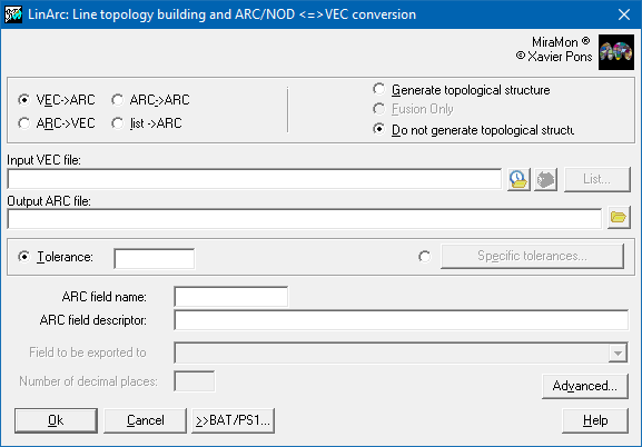
Dialog box of the application
Syntax
Syntax:
- LinArc 1 F_Arc_in F_Vec [NDigits] [/TAULA] [/CAMP] [/SI_EN_BLANC] [/ATRIBUT_CONSTANT] [/ALCADA] [/AJUST_ENV]
- LinArc 2 OriFile F_Arc_out T_Arc [FieldDescriptor] [FieldName] [Prec] [T_Psgen] [T_Esc] [T_Nod] [T_Allg] [/AJUST_ENV] [/ALGORISME]
- LinArc 3 OriFile F_Arc_out T_Arc [FieldDescriptor] [FieldName] [Prec] [T_Psgen] [T_Esc] [T_Nod] [T_Allg] [/AJUST_ENV]
- LinArc 4 F_Arc_in F_Arc_out
- LinArc 5 OriFile F_Result Minimum_threeshold Miaximum_threeshold PointsDecade
Options:
- 1:
Converts an ARC file to a VEC file.
- 2:
Converts VEC or ARC/NOD files to an ARC/NOD family by means of topological structure. It allows an extended syntax to specify the different tolerances.
- 3:
Converts a VEC file having implicit topology to an ARC/NOD family.Option 4:
- 4:
It joins pairs of arches with the same thematic attributes which share a node and, at the same time, no other arch coincides with the node.
- 5:
Analysis of minimal distances between vectors. Studied distances are within the interval [ThresholdMin,ThresholdMax] and the histogram defines PointsDecade intervals.
Parameters:
- F_Arc_in
(Arc file -
Input parameter): It is the name of the input ARC file
- F_Vec
(VEC File -
Output parameter): Transformed VEC file
- NDigits
(Number of digits -
Input parameter): Is the coordinates digital number; default is 6.
- OriFile
(Origin File -
Input parameter): Is the name of a VEC file (with or without extension), of an ARC file (with extension) or of a list file (with extension different than VEC and ARC) that is described below. In this last case FieldDescriptor and FieldName are ignored.
- F_Arc_out
(Arc file -
Output parameter): It's the name of the output ARC file
- T_Arc
(Archs Tolerance -
Input parameter): Distance that a vertex is moved (Fig 1.b1) or segment can be folded, generating a new vertex (Fig 2.b2) to connect to another. (Implies a relationship between an arc and others.)
- FieldDescriptor
(Field Descriptor -
Input parameter): Is a character string (needs quotes if it has spaces) that describes the field Attribute (maximum 40 characters); the default is blank.
- FieldName
(Field Name -
Input parameter): Is a character string (maximum 10 characters) that will be used as the field name in the database file; the default name is ATR_VEC_?, where ? can be L, F or C depending on whether the attributes are integer values, floating point values or character strings.
- Prec
(Precision -
Input parameter): Minimum distance between vertices. It must be a very small value, almost infinitesimal.
- T_Psgen
(Pseudogeneralization tolerance -
Input parameter): Tolerance to remove vertices situated upon the same line. (It is a definition local to each arc).
- T_Esc
(Undershoot tolerance -
Input parameter): It is the maximum distance an arc can be extended to connect to others. (It implies a relationship among one arc and the others.)
- T_Nod
(Node snap tolerance -
Input parameter): Minimum distance between nodes. It is the distance from where one node absorbs or is absorbed by its neighbours. (This implies a relationship among one node and the others.)
- T_Allg
(Dangle tolerance -
Input parameter): Arcs shorter than this tolerance will be removed if they present one or two end nodes. (It is a definition local to each arc.)
- F_Result
(Result File -
Output parameter): Is the name of the CSV table (text separated by ";") containing the histogram of distances and the distances VEC file.
- Minimum_threeshold
(Minimum threeshold -
Input parameter): Minimum threeshold used in the minimal distances analysis
- Miaximum_threeshold
(Maximum threeshold -
Input parameter): Maximum threeshold used in the minimal distances analysis
- PointsDecade
(Points Decade -
Input parameter): PointsDecade
Modifiers:
/TAULA=
(Table name)
Set database table to be exported in a VEC format. To learn more about the values of these parameters follow the considerations in general syntax. (Input parameter) /CAMP=
(Field name)
Set database field to be exported in a VEC format. To learn more about the values of these parameters follow the considerations in general syntax. (Input parameter) /SI_EN_BLANC=
(Blank field)
Sets the VEC exportation behaviour when the attribute do not exist in the database (blank field). Can be "CONSTANT" to write a constant value, "ID_GRAFIC" to write graphic identificator or "IGNORAR" to ignore vectors without attribute (default value). (Input parameter) /ATRIBUT_CONSTANT=
(Constant value)
Sets a constant that is going to be write as object attribute when exporting to VEC format. If it is used in combination with /TAULA=, /CAMP= and /SI_EN_BLANC=CONSTANT is the attribute that is going to be used when there is no data (blank field). (Input parameter) /ALCADA=
(Height)
Sets which of the possible heights are used in the VEC. To learn more about the values of this parameter follow the considerations in general syntax. (Input parameter) /ALGORISME=
(Algorithm of topological structuring)
This modifier is used to determine the algorithm that the application will use to detect possible intersections between the segments of linear elements and polygon edges during the topological structuring. See Available algorithms for topological structuring (/ALGORISME) for a more detailed explanation and suggestions on situations in which one or another algorithm is more appropriate.- ESCOMBRATGE (sweep): Based on the intersection of Bentley-Ottmann segments. For lines that intersect at new vertices.
- DIRECTE (direct): Based on scanning the intersections of each segment against all others. For explicit polygons or for layers with implicit topology (intersections already converted to vertices).
- AUTOMATIC: The program automatically decides which of the two algorithms to use. Sometimes it is slower than the faster of the previous two.
(Input parameter) /AJUST_ENV (Ajust envelope) Ajust the envelope documented in the layer metadata to the minimum rectangle. (1,2,3 options). (Input parameter)
This application support REL v.4 format and ARC v. 1.1 format with or without 3D coordinates.
Idrisi is a program © of J.Ronald Eastman and Clark University.
MiraMon® is a program © of Xavier Pons.