-
 CorRad: Radiometric correction of Remote Sensing images
CorRad: Radiometric correction of Remote Sensing imagesThe program has been prepared for images Landsat (MSS, TM, ETM+, OLI,...), SPOT (XS), Sentinel-2 (MSI), etc, and can be used for almost any other spatial or airborne sensor by using files of RAD type (see description below). These files are very simple to write. As an example some tables with calibration parameters for Landsat-7 ETM+ are supplied.
As for the visible and non-thermal infrared spectral regions, the model of radiometric correction which has been implemented in this program is based on the model proposed by Xavier Pons and Lluís Solé-Sugrañes in the article:
This model has been successfully used in later words of several authors:
Regarding the thermal infrared spectral region, refer to http://ltpwww.gsfc.nasa.gov/IAS/handbook/handbook_htmls/chapter11/chapter11.html the model of conversions of radiances to temperatures.
In the current implementation, however, several improvements such as the consideration of projected shadows, the use of different rescaling factors depending on the different spectral bands, etc., have been included.
This help text only pretends to give an insight in the program use, without getting deeply into the discussion of the justification and foundations of the formulation of the algorithm. If you are interested in these aspects please refer to the article cited above.
For visible and thermal infrared spectral regions, in essence, this model of radiometric corrections converts an image with values (DN) which are proportional to the radiance received by the sensor into an image in which values are reflectances. As it is known, radiance values are usually distributed in the interval [0,1] (or in [0,100] if expressed in percentage). However, in order to avoid the use of files of "real" type (="float"), when the original data does not have a precision superior to 8 bits, the program writes the results in a file of "byte" type. The program allows to rescale the values to the interval [0,255] in the form the user finds more adequate.
The model of radiometric correction takes several factors, among others, into account: relief (incidence angles and projected shadows), solar position, Earth-Sun distance in the moment of image capture, the decrease in radiation in its way down and up because of the atmosphere, and standard parameters for each channel such as atmospheric optical density, exoatmospheric solar irradiance and sensor calibration. The program performs the correction for all the multispectral bands, at the same time, in a single execution, but if desired it can be done for a single band.
Auxiliary images of lighting and shadows
For the topographic correction part of the model, the program needs two auxiliary images derived from the digital elevation model and solar position: The first one will have the cosines of the incidence angle of the solar radiation as pixel values. The second one will have the solar azimuth with which the image was captured, that is the elevation of the sun which cause the projected shadows in each pixel (see the related applications below). These auxiliary images may be generated temporarily or may be provided by the user. It must be borne in mind that the program assumes that the solar position relative to the center of the field is unique for all channels, that different bands can have different pixel side (with corresponding coherent Digital Elevation Models (DEMs)) or even different scope, but not a different scene center. If this condition is not verified, band to band correction will be needed.
These two auxiliary images (which are usually generated, used and are deleted) can be kept if desired, indicating it explicitly with the /CONSERVAR_MDT parameter or the corresponding activation button in the dialog box. If using some already created, derived from the same MDE it is necessary to use options 3 or 4.
Manual atmospheric correction
The manual atmospheric correction is based, when the 1994 model is followed, on the substraction of the lowest radiometric values for each channel. This value is named Kl. When determining Kl it is not recommended to do it 'blindly' by assigning the minimum value of the histogram. Instead, it is recommended to visually inspect the zone with the minimum values in order to determine whether it makes sense or not that it has such low values. For instance, if the image presents zones with no data (0 value) or with punctual low values because of a malfunctioning of the sensor, we will not assign these values to Kl. A visual query of these values with MiraMon (query by attributes on the lowest values for each channel) has proved to be very useful in the determination of Kl. Finally, you should remember that the value of Kl to be applied in an image without neither water nor hard shadows (soft relief in relation to solar elevation) may even be below the minimum value of the image. The Kl values for each side are entered in a text file that can be easily created from the "Create or modify RAD file" button.
Automatic atmospheric correction
The automatic atmospheric correction is based, when following the 2014 model, on the adjustment of the tau and La parameters (only atmospheric contribution of the radiance received by the sensor) through the known reflectance in reference zones, typically in zones pseudo-invariants (PIA) so that they are not dependent on a specific date, obtained from other remote sensors or with field radiometers. These reference values are given in percentage in the main table of the polygon file and it is necessary to provide a field (identified with the band suffix) for each band that you want to correct.
Angles
Although this correction model works with incidence angles inferior to 90 degrees, it is more realistic to assume that with angles that are close to this value the model can not be assumed to be lambertian. Therefore, it is necessary to indicate the angle, in degrees, from which the correction model will not be applied (e.g. 73, 70, etc).
The sensors currently supported, with calibration parameters according to the latest bibliographical reviews, are those included in the file m_atmos.rad:
In order to work with a sensor not present in the previous list it will be necessary to enter the necessary parameters in a user file, created in the program directory, u_atmos.rad, with the same structure as u_atmos.rad:
These parameters must be place in a section named [CALIBR], under keys named:
where 'x' indicates the number of the spectral band.
In any case a specific one can be defined in a supplementary RAD file, indicated by the /F_CALIB= parameter on the command line, similarly, within a section named [CALIBR], under the key x_DN2Rad.
In addition, there can be another section named [SENSOR] with a key:
This information should also be well documented in the metadata of the image to be corrected, in which case the sensor calibration file is unnecessary.
Example of a *.RAD file:
  [SENSOR]
  Titol=CASI Sensor. Configuration for flight dated 8-11-1994.

  [CONFIG]
  NBand=3
  1_lambda_inf=0.4973
  1_lambda_sup=0.5044
  2_lambda_inf=0.5970
  2_lambda_sup=0.6042
  3_lambda_inf=0.7085
  3_lambda_sup=0.7157

  [CALIBR]
  1_S0=1911.254
  1_tau0=0.449
  1_tau0_ret=0.284
  2_S0=1745.934
  2_tau0=0.279
  2_tau0_ret=0.228
  3_S0=1388.889
  3_tau0=0.234
  3_tau0_ret=0.208
From application version 5, this *.RAD file format must have a section that identifies the corresponding version:
  [VERSIO]
  Vers=5
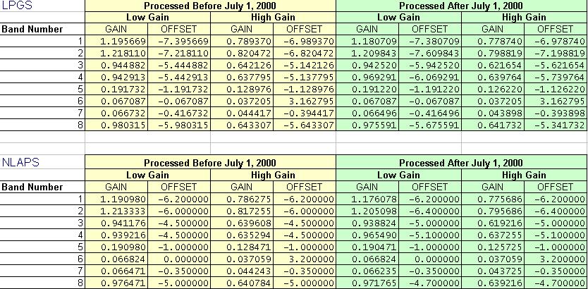
Examples of calibration parameters for Landsat-7:
The result of the radiometric correction is given in reflectances on the ground (BOA is the acronym) and as a percentage. Reflectance can have values between 0% and 100%, although they will usually be below 50%. Pixels where the model cannot provide correct data are conveniently assigned a NoData value: incidence angles greater than 90° or the user-specified Lambertian limit angle, pixels in the shadow of other pixels, or, very rarely, anomalous reflectances (greater than 1, usually due to poor registration between the images and the MDE or snow/clouds), NoData areas in the original image or MDE, etc.
Examples:
318.3 will cause saturation from reflectance values starting at 0.801
510.0 will cause saturation from reflectance values starting at 0.500
637.5 will cause saturation from reflectance values starting at 0.400
In byte case, saturated reflectances are assigned the value 254. Value 255 (NoData) is reserved for pixels where the model can not give correct data. For instance, where incidence angles are superior to 90 degrees, or to the lambertian angle indicated by the user, etc, cases that previously have been explained.
In some images, specially in MSS images processed by EURIMAGE, it is necessary to perform a lineal transformation to the data prior to its correction. This is due to the fact that the histogram of the original data has been stretched with aesthetic purposes. It is necessary to modify the parameters of the calibration line in the metadata.
ATTENTION: In this case, the Kl specified is supposed to be extracted from the images originally "stretched" and, thus, the program performs the substraction DN-Kl before applying the solicited lineal transformation.
NOTES: