-
 DXFVEC: DXF files import
Direct access to online help: DXFVec
Access the application from the menu:
"File | Import | Vectors and/or databases | DXF -> MMM (PNT, ARC/NOD, POL), VEC"
"File | Export | PNT, ARC, NOD, POL, VEC -> DXF"
Presentation and options
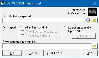
This application performs the conversion between DXF files (obtained with DXFOUT of AutoCAD, export of CorelDraw, etc.) and vectorial files, either topological structured (grouped in a MMM file) or not (VEC format). The application has 7 options, that determine the type of entity to be extracted:
DXFVEC 0:
CONTENTS INFORMATION: Shows a list of the DXF file contents. It reports the number of polylines, lines, arcs, ellipses, circles, solids, points, texts and blocks, broken down by layers. For blocks, each layer lists the names and the number of blocks with that name.
DXFVEC 1:
DXF LINES, POLYLINES, ARCS, ELLIPSES, CIRCLES AND SOLIDS WILL BE TRANSFORMED TO VEC LINES OR POLYGONS. If the program detects that all polylines are closed, either in the DXF definition or because the extreme coordinates are identical, it documents the entities as type "polygon"; otherwise as type "line". The layer of the entity becomes the attribute in the VEC file. The number of vertices in a polyline is practically unlimited. The program uses the command-line tolerance to convert arcs, circles and ellipses to polylines. Tolerance is the maximum allowed error when translating DXF arcs, circles and ellipses to VEC polylines (maximum distance between the arc and the chord). Later DXF versions (AutoCAD 2000) allow curvatures between polyline vertices; tolerance also applies to those objects. If 0 is given, the number of vertices is limited to one per degree. Tolerance can only be given in option 1.
DXFVEC 2:
DXF POINTS WILL BE TRANSFORMED TO VEC POINTS. The layer name of the entity becomes the point attribute in the VEC file.
DXFVEC 3:
DXF TEXTS WILL BE TRANSFORMED TO VEC POINTS WITH TEXT AS ATTRIBUTE. The entity text becomes the point attribute in the VEC file.
DXFVEC 4:
DXF TEXTS WILL BE TRANSFORMED TO VEC POINTS WITH LAYER NAME AS ATTRIBUTE. The layer of the entity becomes the point attribute in the VEC file.
DXFVEC 5:
DXF BLOCKS WILL BE TRANSFORMED TO VEC POINTS. The block name becomes the point attribute in the VEC file.
DXFVEC 6:
DXF LINES, POLYLINES, ARCS, ELLIPSES, CIRCLES AND SOLIDS WILL BE TRANSFORMED TO ARC OR POL FILES, AND POINTS, TEXTS AND BLOCK INSERTION POINTS WILL BE TRANSFORMED TO PNT FILES. A MiraMon Map (MMM) file will be created to group all the new layers.
For options 1 to 5, the application allows to restrict entities to convert to those with numerical attribute, rejecting those with alphanumerical attributes. In case of choosing only numerical attribute entities, the rounding of non numerical attributes can be forced. These 5 options allows 8 entity filters:
- ALL LAYERS ENTITY FILTER (entity filter 1):
- Converts all the entities of a determined typed (line, point, etc.) being in all the layers that have a name compatible with the chosen type. If output attribute type is restricted to numerical integer values, only DXF file layers with integer attribute will be converted (except in the case of text type entities with text as attribute and when is the text that gives the attribute and not the layer, so that it must be integer). The application will keep this value as attribute of the VEC file vectors and will ignore entities situated in layers with non-integer names (an advise will be shown by console when incompatible or rounded attributes exist).
- ONE LAYER ENTITY FILTER (entity filter 2):
- Converts all the entities of a determined typed (line, point, etc.) being in a certain layer that can have as a name an alphanumerical attribute. The application allows to change the attribute of the converted entities (except in text options with text as attribute and blocks, where layer name is only used to filter, and the converted attribute is the own text or the block name). The application converts layer name (or the text string to search) to a numerical attribute or user defined alphanumerical.
- SEVERAL LAYERS ENTITY FILTER (entity filter 3):
- Allows to choose layers and changes to be performed on the attributes of entities converted to VEC. This selection is read from a file of equivalences. The application will usually convert to capital letters text strings that give name to layers, since DXF format keeps the names in capital letters; however, some software (for ex. A/I) do not respect this rule and may write names using small letters. Therefore DXFVEC offers the chance of NOT performing the conversion. Also you should take into account that accentuated letters (capital or small) can not be translated nor compared with the non-accentuated. This entity filter can also be used to extract several layers from a DXF file without the need to iterate many times with the one layer entity filter (entity filter 2); in this case layer name must be equal to the equivalence name in the file of equivalences. See the example below.
- ONE TEXT ENTITY FILTER (entity filter 4):
- This entity filter has sense only for texts and blocks. Permits extracting only DXF texts or blocks with the specified text or block name. In case of options 3 and 5 substitute text will be requested.
- SEVERAL TEXTS ENTITY FILTER (entity filter 5):
- This entity filter has sense only for texts and blocks. Permits extracting only DXF texts or blocks with the text or block name specified in a file of equivalences. As in the former case, if it is required the text or block name will be replaced by another equivalent attribute.
- ALTIMETRY ENTITY FILTER (entity filter 6):
- Assigns the attribute of each entity from the Z coordinate of the first vertex of each DXF file entity.
Only valid for entities of type polyline, line and point.
Entities from all layers are transformed.
- ALTIMETRY LAYER ENTITY FILTER (entity filter 7):
- Equal to the former, but only elements specified in an equivalences file will be extracted.
- BLOCK DESCRIPCION ENTITY FILTER (entity filter 8):
- The previous filters read the entities from the ENTITIES section in the DXF file. On the other filters of the application, and when using blocks, these are extracted with the option 5 as points. Nevertheless, every block presents a geometric description in the BLOCKS section of the DXF file. In some cases it may be interesting to extract every single block description in a VEC file (usually in a 'plane' reference system). This description can be used to generate an EMF that in MiraMon can be associated to points obtained using option 5. Through this way, you get a more faithful visualization. This description could be used to generate an EMF file that, in MiraMon, could be linked as a symbol to the point in the point file obtained with the option 5 and get a better view on MiraMon.
Entity filters 3, 5 and 7 need an equivalence file. An equivalence file is a text file containing couples of equivalences in one column with the following format:
Text_or_bloc_layer_name_1
Substitute_equivalent_name_1
Text_or_bloc_layer_name_2
Substitute_equivalent_name_2
  .
  .
  .
Text_or_bloc_layer_name_n
Substitute_equivalent_name_n
...
GENERAL NOTES ABOUT VEC FILES RESULTS:
- VEC files are ASCII and compatibles with Idrisi software. However, Idrisi does not recognise (at least until v. 4.1) neither attributes of type "string" nor attributes of type "integer" that contain values of type "long" (greater than 32767 or lower than -32768).
- VEC files, when used in Idrisi, even with version 4.x, can give problems if they a zero as attribute.
- Vector-binary Idrisi files have 4 bytes of precision (6-7 significant digits), so, keep in mind when using "CONVERT V" that you can lose precision. We recommend working always with VEC files of type ASCII. MiraMon only supports VEC ASCII files.
- The VEC format can be structured by topology by using other MiraMon tools (VECPNT, Linarc, etc).

Dialog box of the application
Syntax
Syntax:
- DXFVEC 0 Fitx1
- DXFVEC 0 Fitx1 FitxText
- DXFVEC 1 F_DXF F_VEC TypeofAttrib Filter [N_decimal] [Tolerance] [/3D] [/FITX_EQUIV] [/CAPA] [/ATRIBUT] [/TEXT] [/ELIMINA_HIDDEN]
- DXFVEC 2 F_DXF F_VEC TypeofAttrib Filter [N_decimal] [/3D] [/FITX_EQUIV] [/CAPA] [/ATRIBUT] [/TEXT] [/ELIMINA_HIDDEN]
- DXFVEC 3 F_DXF F_VEC TypeofAttrib Filter [N_decimal] [/3D] [/FITX_EQUIV] [/CAPA] [/ATRIBUT] [/TEXT] [/ELIMINA_HIDDEN]
- DXFVEC 4 F_DXF F_VEC TypeofAttrib Filter [N_decimal] [/3D] [/FITX_EQUIV] [/CAPA] [/ATRIBUT] [/TEXT] [/ELIMINA_HIDDEN]
- DXFVEC 5 F_DXF F_VEC TypeofAttrib Filter [N_decimal] [/3D] [/FITX_EQUIV] [/CAPA] [/ATRIBUT] [/TEXT] [/ELIMINA_HIDDEN]
- DXFVEC 6 F_DXF D_MMM [/PER_TIPUS_TOPO] [/NO_DIBUIXAR_BLOCS]
Options:
- 0:
Information on the file contents
- 1:
Lines, polylines, arcs, circles, ellipses and solids -> lines or polygons, depending on whether they are open
- 2:
Points -> points
- 3:
Texts -> points with the text as attribute
- 4:
Texts -> points with the layer as attribute
- 5:
Blocks -> points with the block name as attribute
- 6:
Lines, polylines, arcs, circles, ellipses and solids -> ARC or POL files; points, texts and block insertion points -> PNT files. An MMM map is created.
Parameters:
- Fitx1
(File 1 -
Input parameter): DXF file whose contents will be listed.
- FitxText
(Text file -
Output parameter): Name of a text file that will keep a copy of the information shown on screen. Only available in option 0.
- F_DXF
(DXF file -
Input parameter): Name of the DXF file to convert.
- F_VEC
(Vector file -
Output parameter): Usually the name of the output VEC file. It is the extraction directory when using filter 8.
- TypeofAttrib
(Type of attribute -
Input parameter):
- 1 Integer numbers, ignoring texts and rounding if needed.
- 2 Real numbers, ignoring texts.
- 3 Alphanumeric (texts and numbers) (not valid with altimetry entity filters).
- Filter
(Filter -
Input parameter): Object filter:
- 1 Objects from all layers.
- 2 Objects from a single layer.
- 3 Objects from several layers from a single-column equivalences file.
- 4 One text in any layer.
- 5 Several texts in all layers from an equivalences file.
- 6 Altimetry: the attribute is taken from the Z of the first vertex.
- 7 Altimetry from an equivalences file.
- 8 Block descriptions.
- N_decimal
(Number of decimals -
Input parameter): Number of decimal digits written in the output coordinates. Allowed values: 0 to 15; default is 6.
- Tolerance
(Tolerance -
Input parameter): Maximum tolerated error when translating DXF arcs, circles, ellipses and vertex curvatures to VEC polylines. Only allowed in option 1. Default is 0.
- D_MMM
(MMM map directory -
Output parameter): Directory where the MMM map and its topological files will be created.
Modifiers:
/3D= (3D) 1 means the third dimension of the DXF file should be imported. 0 means it should not. If the parameter is omitted, the program detects whether the DXF is 2D or 3D and chooses the corresponding VEC format. (Input parameter) /FITX_EQUIV= (Equivalences file) Name of the equivalences file for entity filters 3, 5 and 7. If omitted, the file name is asked during execution. (Input parameter) /CAPA= (Layer) Name of the layer to import with filter 2. If omitted, the layer name is asked during execution. (Input parameter) /ATRIBUT= (Attribute) Attribute that replaces the layer name when importing with filter 2. If omitted and /CAPA is given, the same value is used; otherwise it is asked during execution. (Input parameter) /TEXT= (Text) Text (or block name) to import with filter 4. If omitted, it is asked during execution. (Input parameter) /ELIMINA_HIDDEN (Skip HIDDEN entities) Do not import DXF entities marked with HIDDEN style (hidden entities or AutoCAD Hidden linetype). Only applies to options 1 to 5. (Input parameter) /PER_TIPUS_TOPO
(By topological type)
All entities are placed in a single point or arc/polygon file, ignoring the original layer distribution. If this option is absent, each original layer keeps its entities in separate topological files. (Input parameter) /NO_DIBUIXAR_BLOCS
(Do not draw blocks)
Block entities will not be drawn. A point layer with all block insertion points is still created (by default this layer is not visible but it is queryable). (Input parameter)
Arc/Info, AutoCad, CorelDraw and Idrisi are trade marks of its respective
owners.
MiraMon is a trade mark of Xavier Pons.